


OK1TK Czech republic HAM radio station

The remote controller for the automatic antenna tuner ATU-100 is still under development. The last tests show that the most difficult part – to transfer the display data via bluetooth – is most probably possible as you can see on the video below. But as you can also see there is still lots to do and improve.
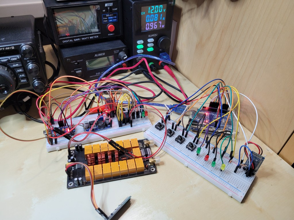
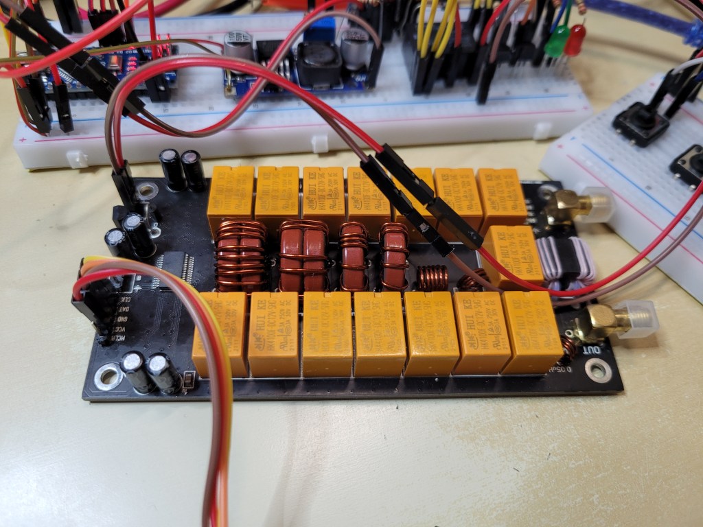
Also the picture below shows that it might work with some small improvements. The OLED display in the video and and on the pictures below shows the data captured on the tuner’s I2C BUS using ESP32 microcontroller which proccessed the data and transfer the data via bluetooth to another ESP32 microcontroller which receives the data and send them to the I2C BUS of an OLED display.
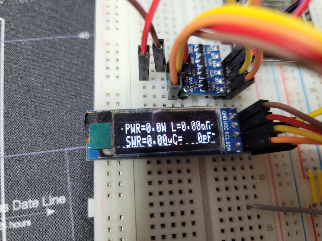

Anyway letš go back to work. And …. if there is someone capable to help with the development in the ESP-IDF let me know.
The third test was to completely test the ATU-100 functionality and that the all buttons control works remotely via Bluetooth. I tried to turn ON/OFF the tuner and then tested the functionality of the TUNE/RESET, AUTO and BYPASS buttons with the corresponding response on the OLED display. The video below shows that the whole functionality works correctly. All the responses were visible on the OLED display:
RESET -> short prest of the RESET/TUNE button
TUNE -> long press of the RESET/TUNE button
AUTO -> press of the AUTO button (indicated by the „.“ between the PWR and L)
BYPASS -> press of the BYPASS button (indicated by „_“ between the PWR and L)
After the buttons functionality test I tried to enter the both test modes described below.
FAST TEST MODE
To enter the Fast Test Mode we press at the same time TUNE/RESET + AUTO + BYPASS buttons and then we apply the POWER button to turn the ATU-100 ON.
The Fast Test Mode switches the all relays to the ON state and connects all the inductances and capacitances at once.
In my case I could see the current consumption increased from ca 120 mA to 330 mA (the consumptions includes the Arduino Nano, HC-05, LEDs and tuner together).


THE TEST MODE
To enter the Test Mode we press at the same time AUTO + BYPASS buttons and then we apply the POWER button to turn the ATU-100 ON.
At the Test Mode we can check the inductances and capacitances individually by pressing the AUTO button to decrease the value and BYPASS button to increase the value. By the long press of the TUNE/RESET button we can switch between the inductances test and capacitances test.

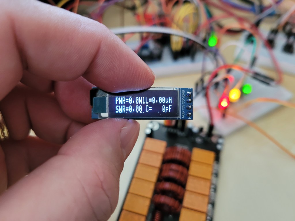


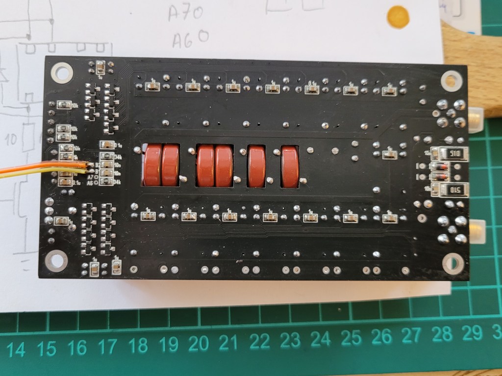

The second test follows up on the previous testing but adds the function of the TUNE/RESET, AUTO and BYPASS buttons of the automatic antenna tuner ATU-100.
Because the tuner uses the negative logic to control the the TUNE/RESET, AUTO and BYPASS function all three LEDs light of the slave module when the tuner is turned ON (logic 1).
By pressing the TUNE/RESET, AUTO, BYPASS the button on the muster module the appropriate LED on the slave button is switched OFF (logical 0).


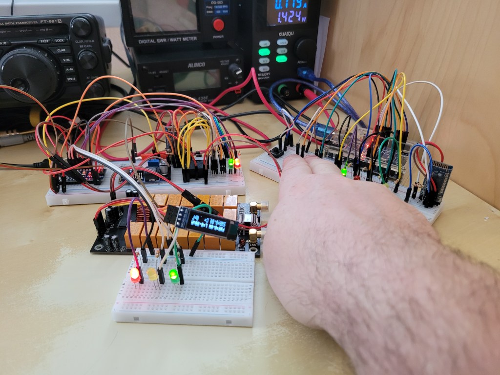
The first successful test of the bluetooth remote controller for N7DDC ATU-100. The first test shows just only the test of turning ON/OFF the N7DDC automatic antenna tuner via bluetooth HC-05 modules and using an Arduino UNO as the master controller with POWER, TUNE/RESET, AUTO and BYPASS buttons and an Arduino NANO as the slave controller with a green control (ON/OFF) LED and a bistable relay to switch ON/OFF the +12V ATU-100 power supply.




Location: Croatia, Island of Hvar, Ivan Dolac, IOTA: EU-016, Loc: JN83HD.
I was allowed to raise my antenna next to our apartment so I moved to the center of Ivan Dolac. Therefore I am able to work directly from our apartment and that’s much more easier. Anyway 20W seems to be bit less then I would need to make more SSB contacts so I switched to FT8 and was able to work some interesting DX locations, e.g. Malawi, Brazil, Uruguay on 10m and 15m.

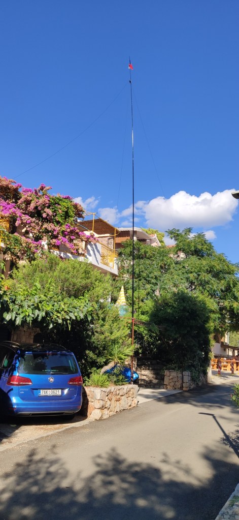
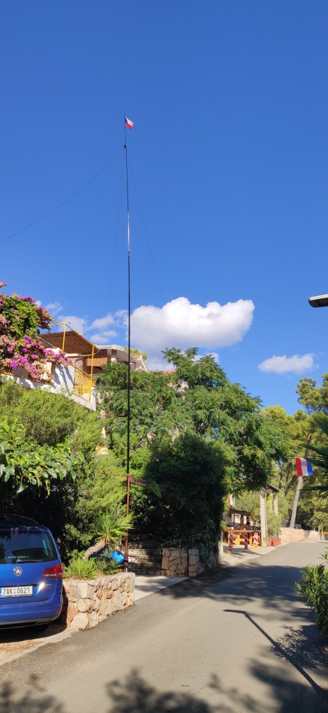

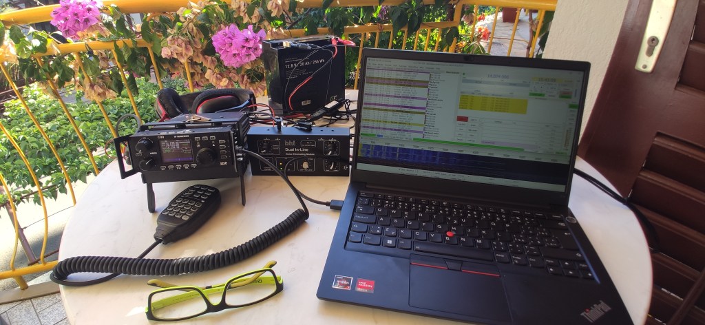
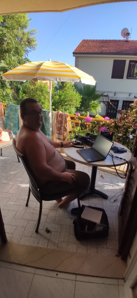


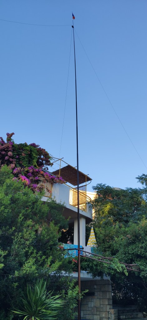
Location: Croatia, Island of Hvar, Ivan Dolac, IOTA: EU-016, Loc: JN83HD61.
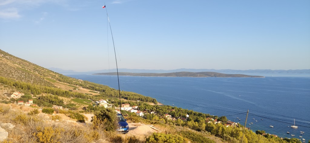
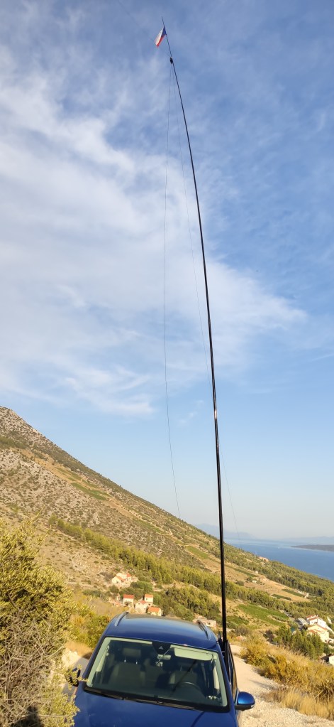
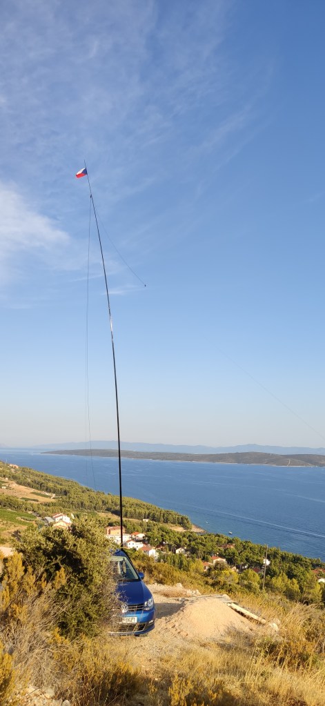
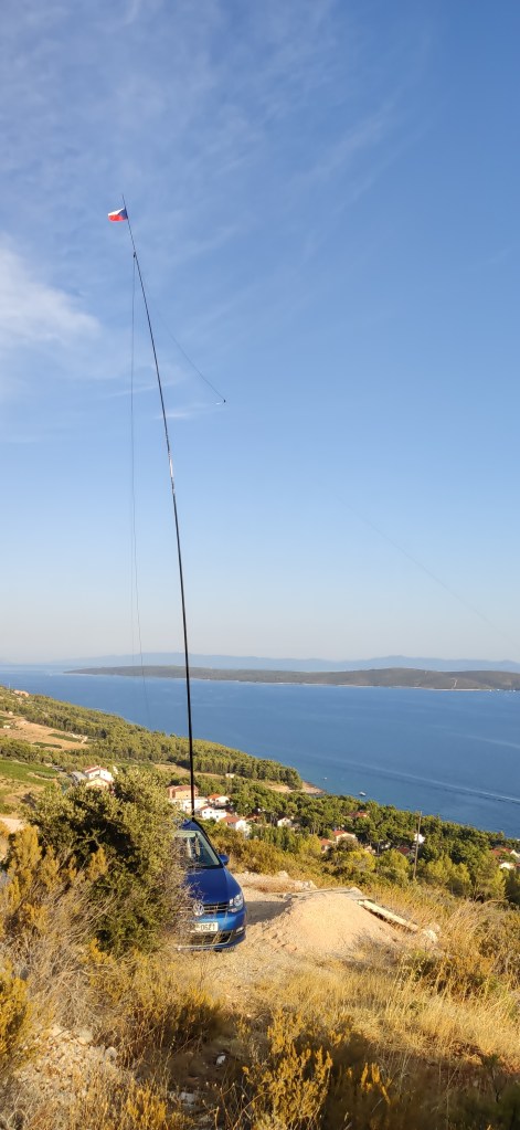
My first test of my mobile equipment in Croatia was not quite successful. I underestimated the Croatian soil full of small stones so I was not able to use my plastic threaded pins tu support the Spiderbeam mast. I had to improvise and use my car as support. Also the conditions were not very good so I was able to make 2 QSO only with M0MCV to London and EA9KB to Ceuta.
Although the conditions were not good the view from my location was really wonderful.


Within the July 2nd till July 8th I worked portable in the small village of Karlov. Karlov is located ca 120 km NE from Prague in the mountains called Jizerske hory where the highest point is 1124 m.a.s.l.






Unfortunately my working conditions were not very good due to the high local QRM especially on 20m where it was up to S7. The equipment used was the same as last time: Xiegu G90 (20W), BHI Dual Inline DSP, Aerial-51 model 404-UL ultralightweight, asymmetrical dipole HF antenna with the 12m high Spiderbeam pole.
All calls are logged on the qrz.com (OK1TK/P).
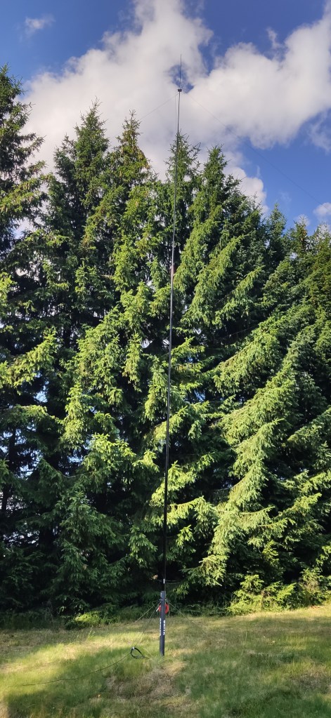


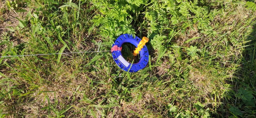
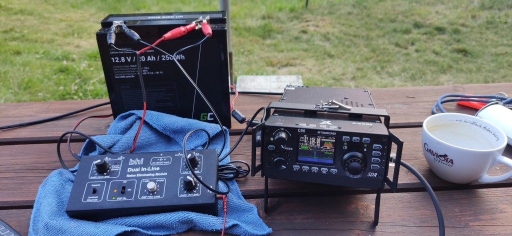
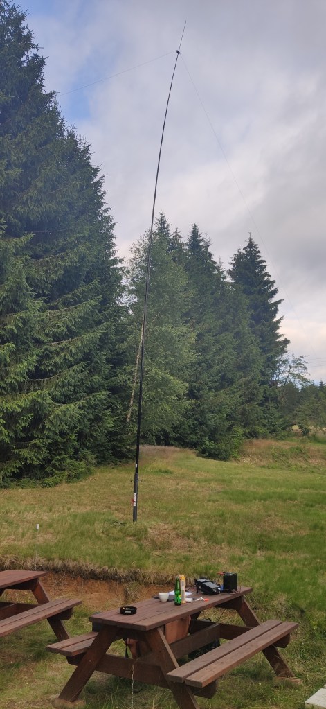


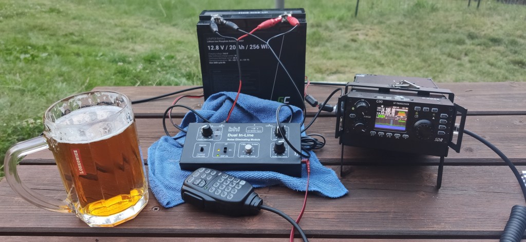
Today it was my first HF portable operation ca 3,5km from the center of the town Holice. I tested my new Aerial-51 model 404-UL ultralightweight, asymmetrical dipole HF antenna with the 12m high Spiderbeam pole. I used my Xiegu G90 with 20W output power.
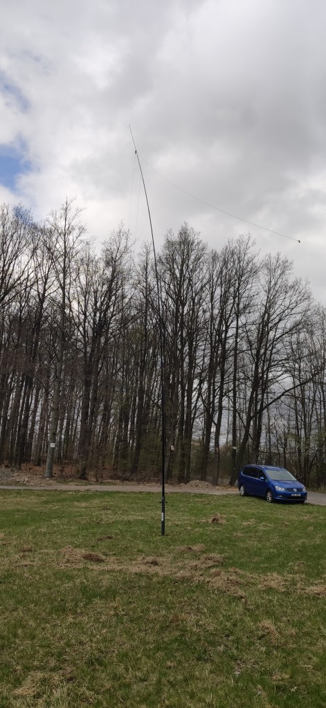
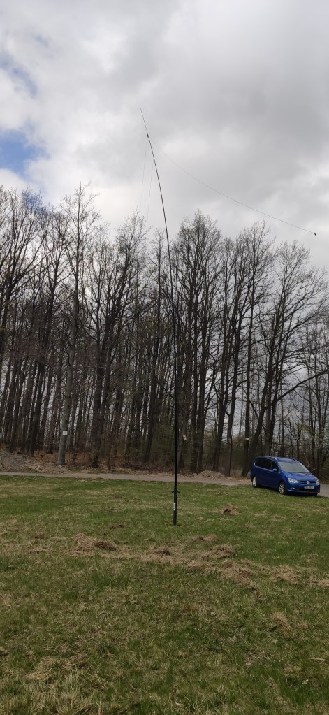

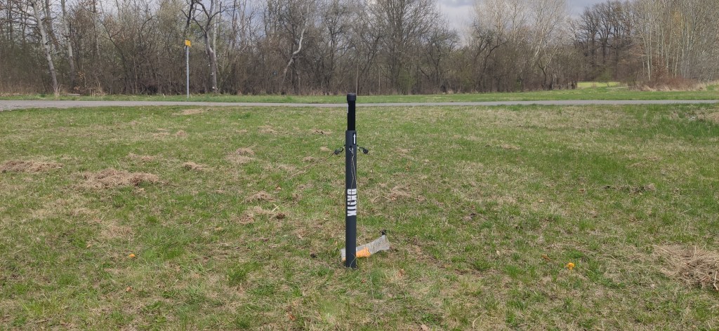
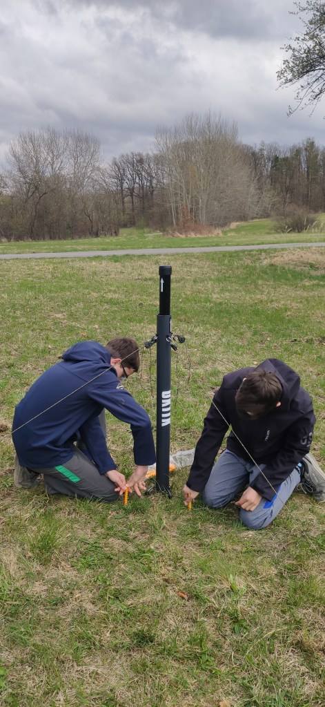
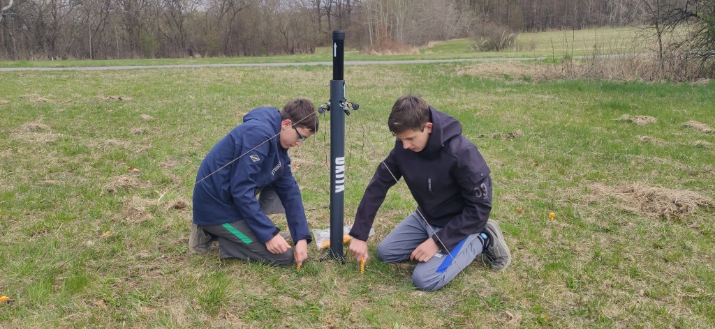
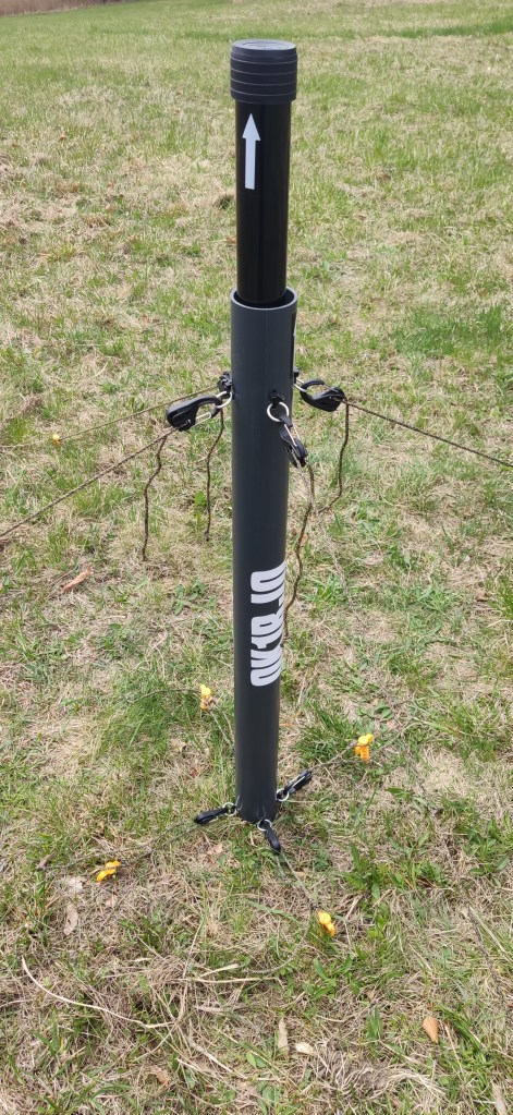
My sons (OK1RJO) helped me to setup the antenna with hombrew antenna pole holder.
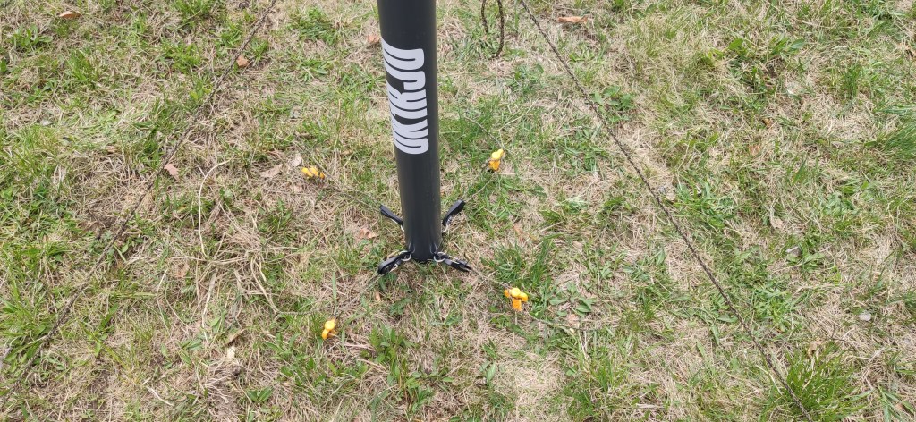
The homebrew antenna pole holder inspired by the 2nd version designed by VE3TWM was performing very well despite the relatively windy weather. It was used without any other support for the pole. To avoid the pole bending it would be better to use additional Kevlar guy line or lines.




QSO with OE2MRN on 40m band.
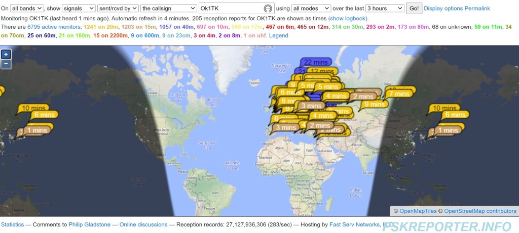
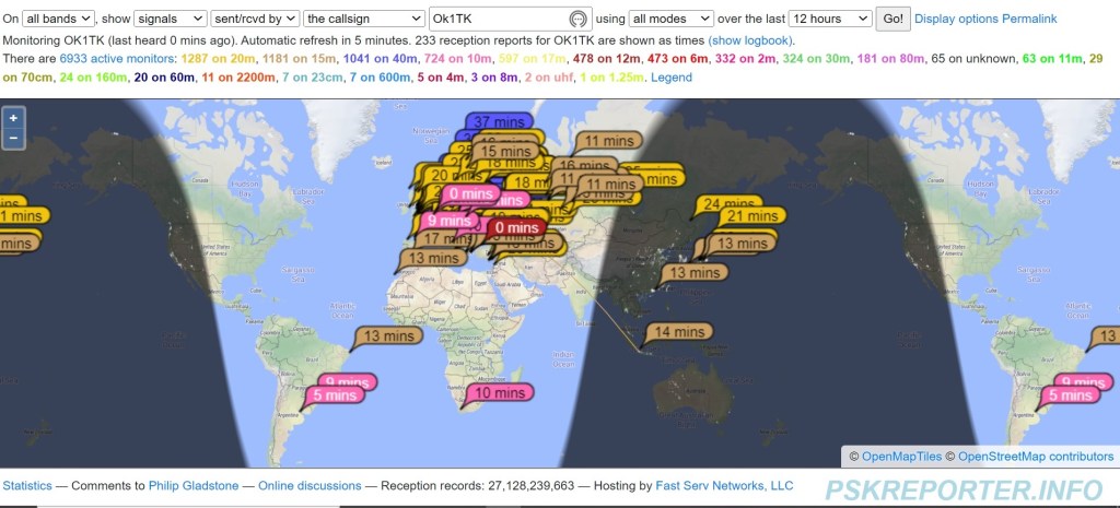
I tested the digital modes at the end as well. Due to the limited battery capacity of my notebook it was fast test and the results from PSK reporter are below.

Have a WordPress.com account? Log in now.

