1. Check the COM Ports
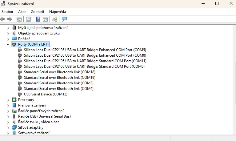
After connecting the radio via USB, first check the assigned COM ports in Windows Device Manager → Ports (COM & LPT). In my case:
| FT-991A | FTX-1 |
| COM5 – Enhanced COM Port | COM8 – Enhanced COM Port |
| COM6 – Standard COM Port | COM11 – Standard COM Port |
With the FTX-1, an additional USB Serial Device (COM12) also appears. It is not used for this setup.
Note: COM port numbers are assigned by Windows, so they may be different on your PC.
2. N1MM Logger+ Configuration
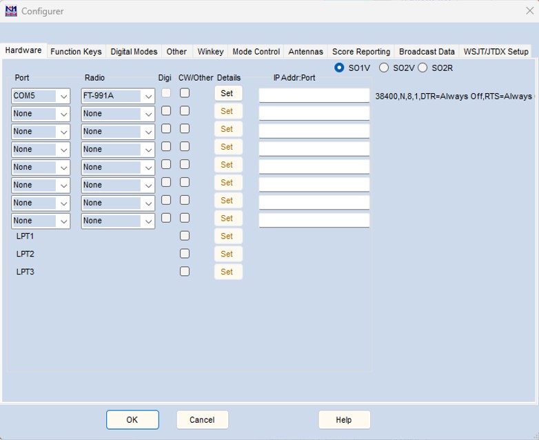
For this setup, I used a fresh installation of both N1MM Logger+ and MMTTY, with no previous settings carried over.
In the main N1MM Logger+ window, go to:
Config → Configure Ports, Mode Control, Winkey, etc…
In the Hardware tab:
| • Operating mode: SO1V (Single Operator, One VFO) |
| • Port: COM5 (Enhanced COM Port) |
| • Radio: FT-991A |
| • Digi: unchecked |
| • CW/Other: unchecked |
Note: Your COM port number may be different.
3. Yeasu FT-991A COM Port Settings
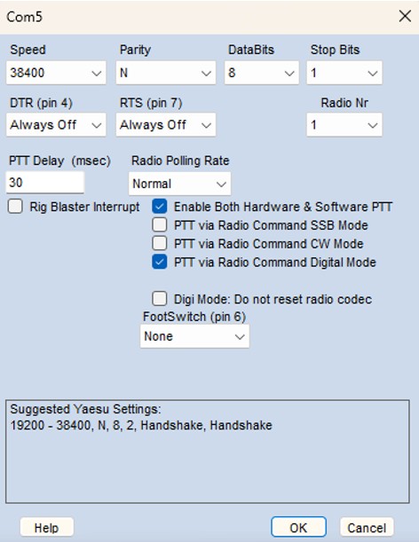
After clicking Set next to the FT-991A COM port, configure the port as shown below:
| • Speed: 38400 |
| • Parity: N |
| • DataBits: 8 |
| • Stop Bits: 1 |
| • DTR (pin 4): Always Off |
| • RTS (pin 7): Always Off |
| • Radio Nr: 1 |
| • PTT Delay: 30 ms |
| • Radio Polling Rate: Normal |
| • Enable Both Hardware & Software PTT: checked |
| • PTT via Radio Command Digital Mode: checked |
Leave the other options unchecked and click OK.
Note: Not all of these settings necessarily affect RTTY operation, but this is the configuration I used and successfully tested.
4. Digital Modes – MMTTY Setup
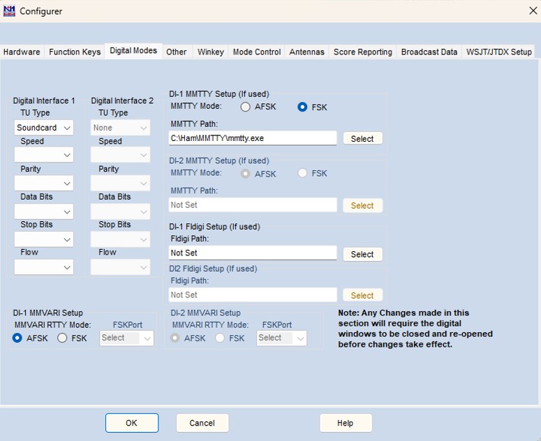
Open the Digital Modes tab and configure DI-1 MMTTY Setup as follows:
| • Digital Interface 1 – TU Type: Soundcard |
| • MMTTY Mode: FSK |
| • MMTTY Path: C:\Ham\MMTTY\mmtty.exe |
Use Select to locate your mmtty.exe file. The standard installation location is usually C:\Ham\MMTTY\mmtty.exe. If you installed MMTTY in a different folder, simply select the corresponding path.
Note: For the FTX-1 setup, I used a separate copy of MMTTY. This allows me to keep the working FT-991A configuration unchanged and maintain independent MMTTY settings for both radios. This will be explained in the FTX-1 section.
5. Mode Control – MMTTY Setup
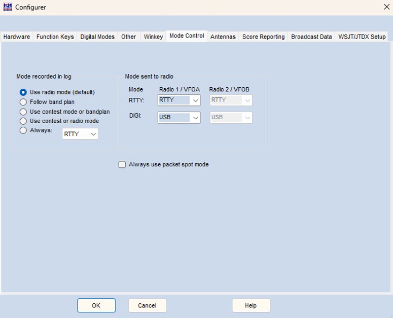
Open the Mode Control tab. No special changes were required here for this RTTY setup, but the settings are included for reference and to show the complete configuration.
| • Mode recorded in log: Use radio mode (default) |
| • RTTY – Radio 1 / VFO A: RTTY |
| • DIGI – Radio 1 / VFO A: USB |
| • Always use packet spot mode: unchecked |
These are the default settings used in my installation. No changes were necessary here for RTTY operation.
6. MMTTY Configuration

Now we will move on to the MMTTY configuration itself.
In the MMTTY RTTY Engine window, click Option(O) in the top menu. We will configure the required MMTTY settings step by step as shown below.
7. MMTTY – Demodulator
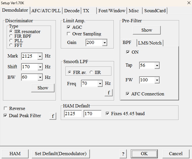
In Option(O) → Setup MMTTY, open the Demodulator tab.
No special changes were required here. Just check that the basic RTTY parameters are set as follows:
| • Mark: 2125 Hz |
| • Shift: 170 Hz |
| • Fixes: 45.45 baud – checked |
The Mark (2125 Hz) and Shift (170 Hz) values are also set to the same values in the radio.
The other settings were left at their default values as shown in the screenshot.
8. MMTTY – Decode
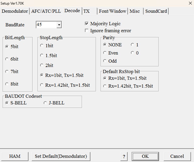
Open the Decode tab.
No changes were required here. The default settings were used and are shown in the screenshot for reference and completeness of the configuration.
9. MMTTY – TX
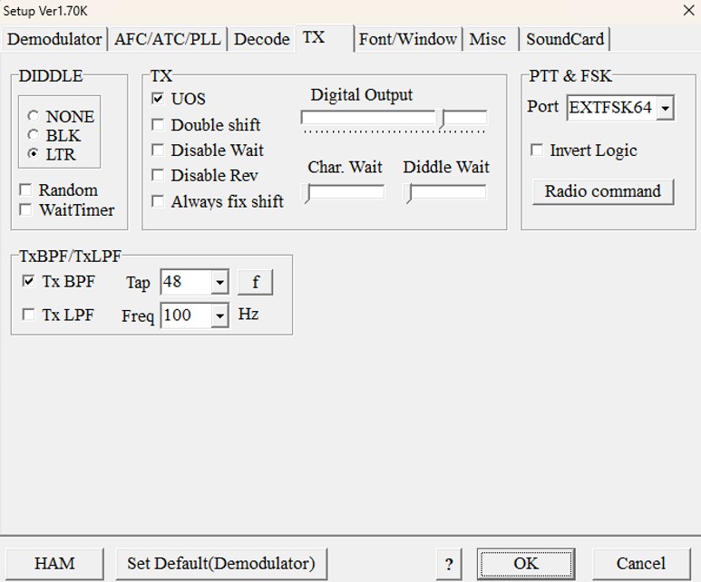
Open the TX tab. This is an important part of the FSK configuration.
Under PTT & FSK, change the Port setting to:
EXTFSK64
The other settings were left unchanged as shown in the screenshot.
Do not close the Setup window yet. Click Radio command – this opens another configuration window, which we will set up in the next step.
10. MMTTY – Radio Command
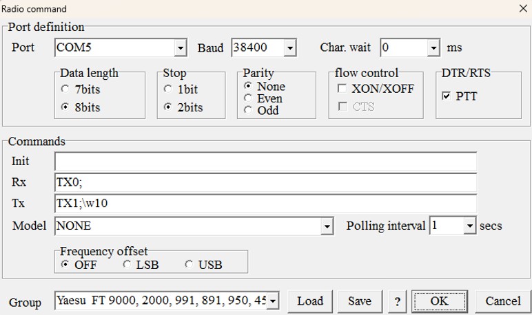
In the Radio command window, configure the communication with the FT-991A as follows:
| • Port: COM5 (Enhanced COM Port) |
| • Baud: 38400 |
| • DTR/RTS – PTT: checked |
| • Frequency offset: OFF |
| • Group: Yaesu FT 9000, 2000, 991, 891, 950, 450 |
The Data length, Stop, Parity and Commands settings were left unchanged and should be set as shown in the screenshot.
The settings shown here are the ones used in my working FT-991A configuration. Click OK when finished.
11. MMTTY – Misc
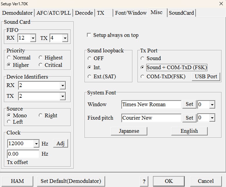
Open the Misc tab and use the following settings:
| • Device Identifiers – RX: 2 (see below) |
| • Device Identifiers – TX: 2 (see below) |
| • Clock: 12000 Hz |
| • Sound loopback: Int. |
| • Tx Port: Sound + COM-TxD (FSK) |
The Device Identifiers determine which sound devices MMTTY uses for RX and TX. In my setup, both are set to 2.
These numbers are assigned according to the audio devices available in your PC, so they may be different on another system. The Device Identifiers are linked to the devices selected on the SoundCard tab – changing the identifier effectively selects a different audio input or output device.
If no received signal appears in the MMTTY display even though the correct sound card appears to be selected, check the RX Device Identifier and try the available values until the radio’s audio signal appears. This was useful in my setup when identifying the correct USB audio input from the radio.
I set the TX Device Identifier to the same value as RX (2). For this FSK configuration, the TX audio device is less important than it would be for AFSK, since the actual RTTY keying data is sent via FSK rather than being generated as an audio tone by the sound card.
The Clock is set to 12000 Hz. This is the MMTTY audio sampling rate used by the demodulator and 12000 Hz is a commonly used/recommended setting for MMTTY with N1MM Logger+.
Finally, under Tx Port, select Sound + COM-TxD (FSK). This is the setting used in my working FT-991A configuration.
12. MMTTY – SoundCard
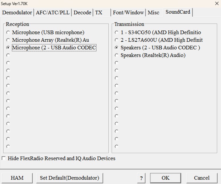
Open the SoundCard tab and select the USB audio device belonging to the FT-991A.
| • Reception: Microphone (2 – USB Audio CODEC) |
| • Transmission: Speakers (2 – USB Audio CODEC) |
The exact device names may be different on your PC. For Reception, select the USB Audio CODEC associated with the FT-991A. This provides the received audio from the radio to MMTTY for decoding.
In my setup, I also selected the corresponding Speakers (2 – USB Audio CODEC) for Transmission. However, when operating in FSK, the transmission sound device is not required for generating the RTTY signal, since the actual FSK keying is handled separately.
If you have more than one USB audio device connected, make sure you select the one belonging to the correct radio.
13. Yaesu FT-991A – Radio Settings
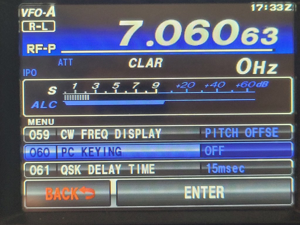
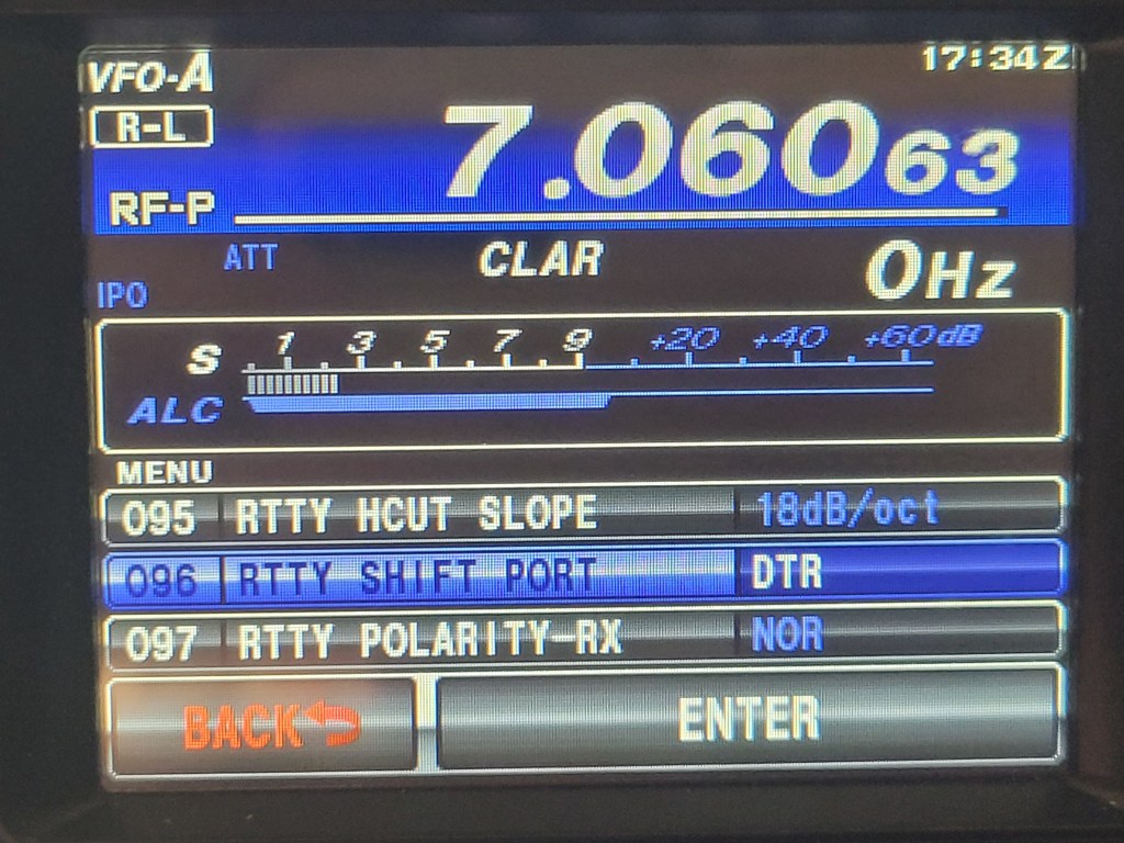
Now we need to configure the FT-991A itself. These settings are essential for correct FSK RTTY operation with the configuration described above.
Open the FT-991A MENU/SETUP and set:
| • 060 PC KEYING: RTS |
| • 096 RTTY SHIFT PORT: DTR |
These two settings are very important. With 060 PC KEYING = RTS, the RTS line of the USB virtual COM port is used for PTT, while 096 RTTY SHIFT PORT = DTR uses the DTR line for FSK shift keying.
This matches the MMTTY/EXTFSK configuration used in the previous steps. The FT-991A operating manual also specifies this RTS/DTR combination for RTTY operation via the virtual COM port.
I also left 097 RTTY POLARITY-RX = NOR (Normal), as shown in the screenshot.
There are still a few important FT-991A settings to check before we are finished – in particular Mark = 2125 Hz, Shift = 170 Hz, and the RTTY-LSB operating mode. We will cover these in the following steps.
14. EXTFSK64 Configuration
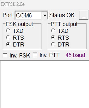
After completing the MMTTY setup, configure the small EXTFSK64 window. It will normally appear automatically after selecting EXTFSK64 under PTT & FSK in MMTTY. If you do not see it, check the Windows taskbar – the window may already be open or minimized.
For the FT-991A, use the following settings:
| • Port: COM6 (Standard COM Port) |
| • FSK output: DTR |
| • PTT output: RTS |
| • Inv. FSK: unchecked |
| • Inv. PTT: unchecked |
The port number may be different on your PC. Select the Standard COM Port assigned to the FT-991A – in my case this is COM6. The EXTFSK64 window should show Status: OK.
For my FT-991A, the working combination is FSK output = DTR and PTT output = RTS. This corresponds to the radio settings configured earlier: 096 RTTY SHIFT PORT = DTR and 060 PC KEYING = RTS.
I left Inv. FSK unchecked. If the FSK polarity is correct, no inversion is required. I also left Inv. PTT unchecked.
Once configured, the EXTFSK64 window can simply be minimized; the settings are remembered for future use.
15. Final Note
The settings described in this guide are based on my own working configuration and have been successfully tested on the air. However, every PC and radio setup can be slightly different – COM port numbers, USB audio device identifiers, drivers, or other settings may vary.
Therefore, some adjustments may be necessary for your particular setup.
I hope this guide helps you get RTTY working with N1MM Logger+ and MMTTY without too much trial and error. I would be very happy to receive your feedback and hear whether this setup works for you as well.

