At the beginning I would like to highlight that I was able to work on this project only thanks to the patient, expert and great supervision and guidance of OK1BVK. Because this was my first Arduino project I really needed his help.
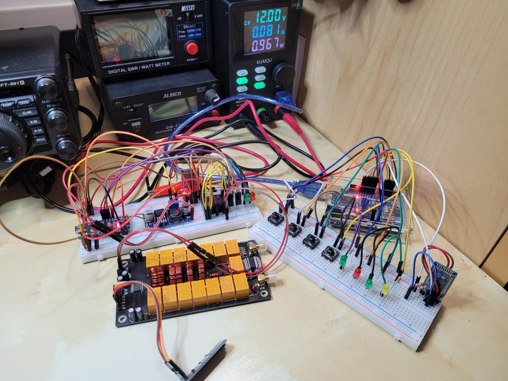
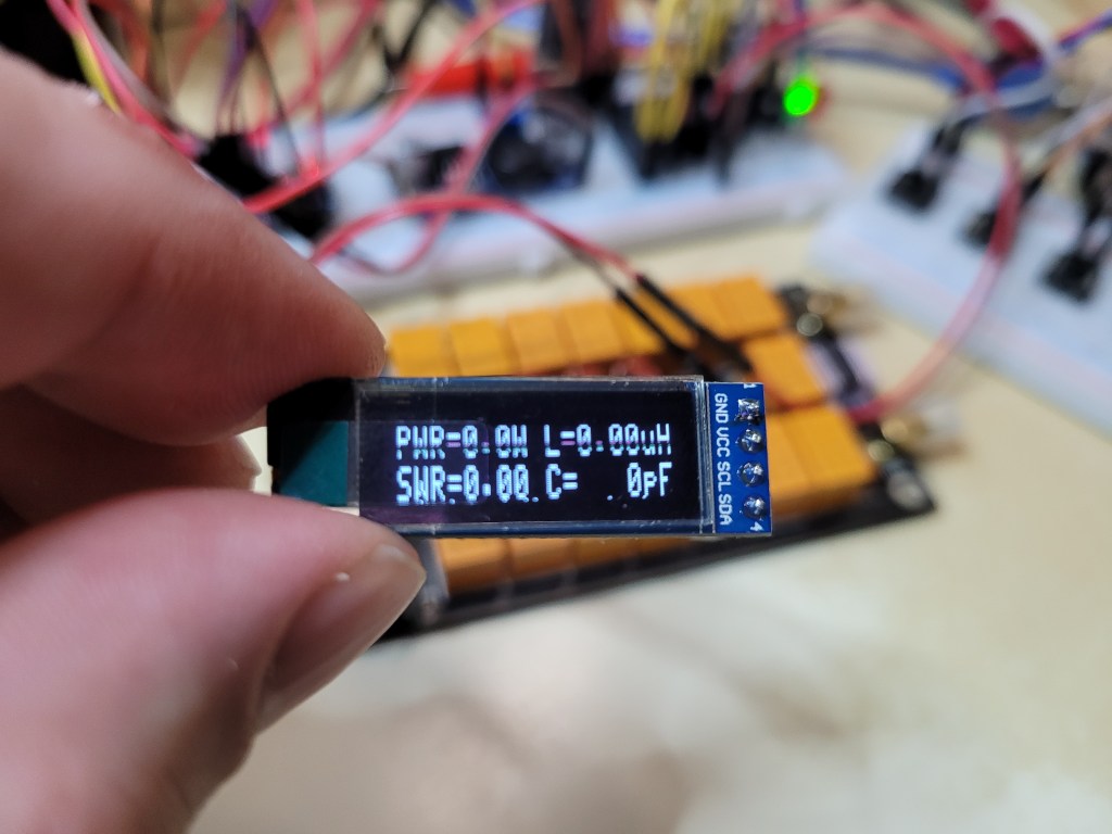
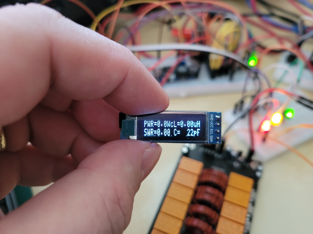
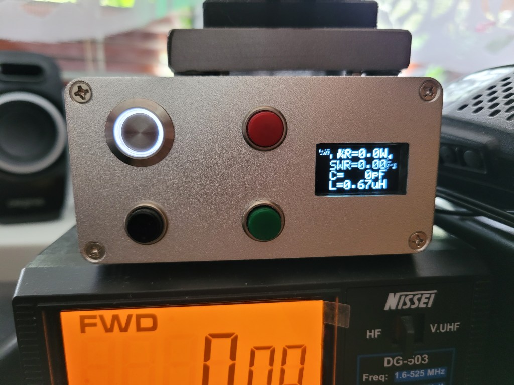
Based on the need to remotely control the well known N7DDC automatic antenna tuner ATU-100 which is currently placed on my balcony I decided to try to control the tuner with Arduino via Bluetooth. The reason why I decided to use wireless communication to control the ATU is that the current solution via wires is not working correctly. The I2C display communication is interfered when my TRX is transmitting on some bands. It works correctly on 20m, 17m, 15m and 10m but unfortunately the lower bands are interfered in my case.
At the beginning I would like to point out that this project covers just the control of the tuner’s buttons. It seems that Arduino alco isn’t able to cover the tuner’s display communication and snip the tuner’s I2C data. Therefore I decided to try to to build the project based on the ESP32 development bords. Anyway someone can be inspired by this Arduino project and can find the solution how sniff and to transfer the display data via bluetooth. If so please don’t hesitate to contact me.
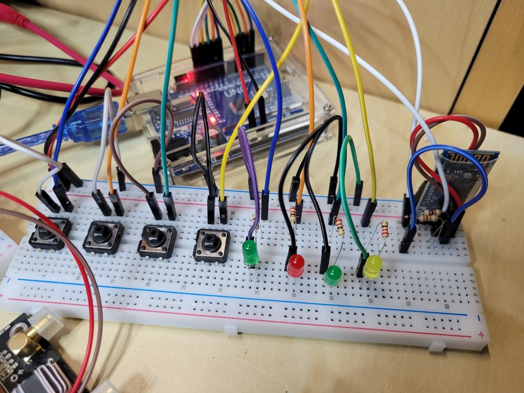
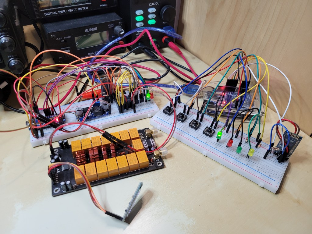
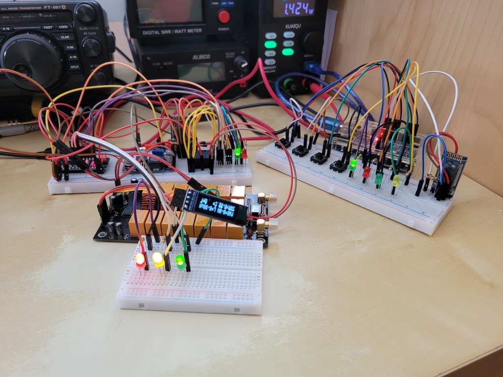
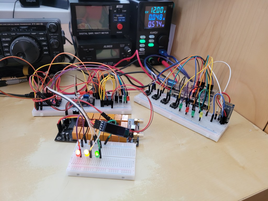
The project itself divided into two separate parts. The first is the Master module and the second is the Slave module. The master module is based on Arduino UNO and is responsible to send the data from its buttons (RESET/TUNE, AUTO, BYPASS) to the slave module via bluetooth.
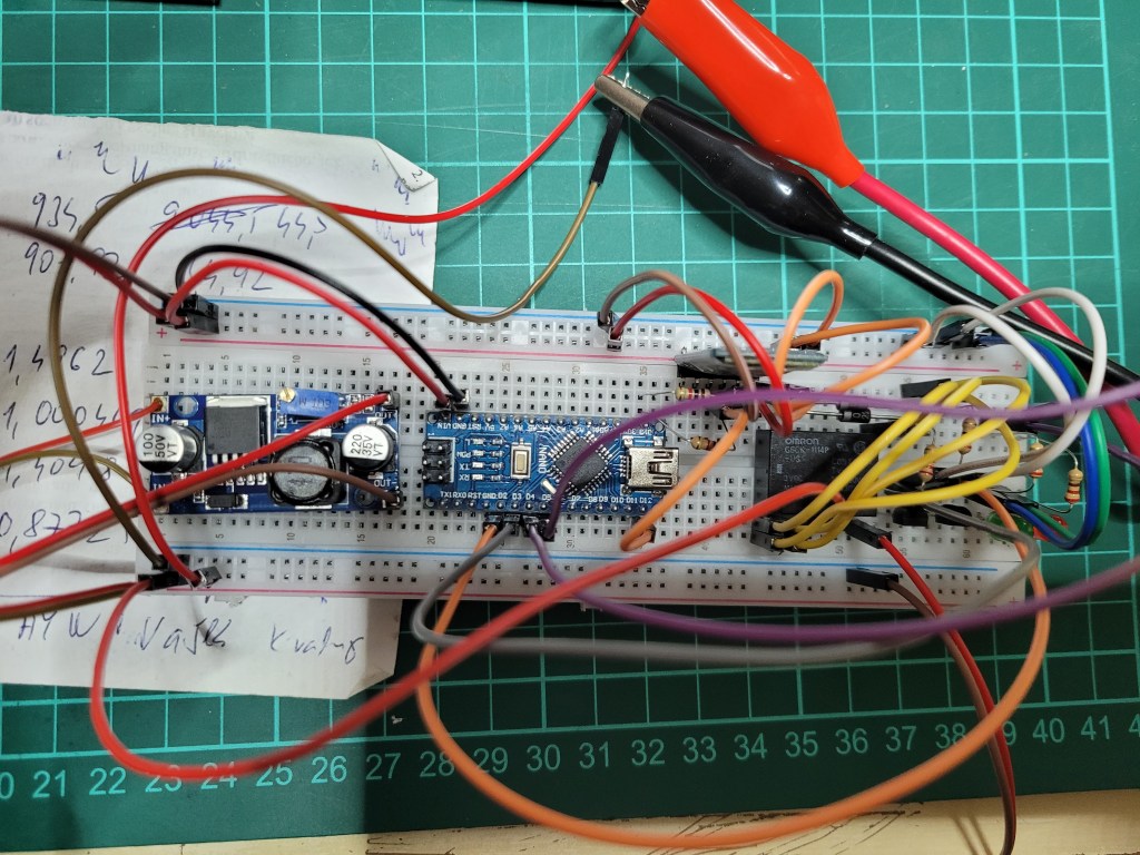
The slave module is based on Arduino NANO captures the bluetooth data from the master module and drives the ATU-100 power control and the RESET/TUNE, AUTO and BYPASS inputs in negative logic.

THE MASTER MODULE

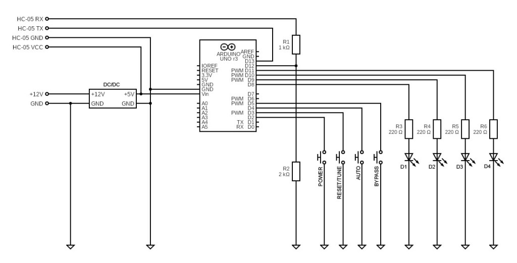
The master module consists of the following components:
| Arduino UNO | 1pc | The Arduino UNO board |
| HC-05 | 1pc | The HC-05 bluetooth module in the master mode |
| DC/DC | 1pc | Step-down converter 12V->5V (e.g. with LM2596) |
| Push nutton | 4pcs | Standard micro push button |
| R1 | 1pc | resistor 1kΩ |
| R2 | 1pc | resistor 2kΩ |
| R3-R6 | 4pcs | resistor 220Ω (can be skipped) |
| D1-D4 | 4pcs | LED various colors (can be skipped) |
Below is the master module electric diagram based on Arduino UNO. The LEDs part consisting of the R3-R6 and D1-D4 can be skipped or replaced by one or two LEDs when the first signals that the tuner is ON and the second signals that one or more of the tuner buttons are pressed (the simmilar solution as on the slave module below).
The master module code for the Arduino IDE:
 | You can download the MASTER_Buttons_FINAL_v15.ino file by clicking on the link on the left or you can copy the code via clipboard from the text filed below. |
/*********************************************************************************************
 * N7DDC ATU-100 All Buttons Bluetooth Remote Control                                        *
 * Final Development testing version v15 (MSTER), 19.03.2023 - OK1TK                         *
 * MASTER_Buttons_FINAL_v15.ino C++ code for the naster module                               *
 *                                                                                           *
 * PWR button fully functional, RESET/TUNE, AUTO, BYPASS buttons fully functional            *
 * (including combinations: AUTO+BYPASS+POWER & RESET/TUNE+AUTO+BYPASS+POWER)                *
 * Power control LED fully functional; RESET/TUNE, AUTO, BYPASS control LED fully functional *
 *********************************************************************************************/

#include <SoftwareSerial.h>                                     // Including SoftwareSerial library

#define	BUTTON_PWR	2                                           // Define pin for the POWER button
#define BUTTON_TUNE 3                                           // Define pin for the RESET/TUNE button
#define BUTTON_AUTO 4                                           // Define pin for the AUTO button
#define BUTTON_BYPASS 5                                         // Define pin for the BYPASS button

#define LED_PWR 8                                               // Define pin for the POWER button control LED
#define LED_TUNE 9                                              // Define pin for the TUNE button control LED
#define LED_AUTO 10                                             // Define pin for the AUTO button control LED
#define LED_BYPASS 11                                           // Define pin for the BYPASS button control LED

#define	BIT_PWR 8                                               // Define value of the 3rd bit = 8 if the POWER button is pressed
#define	BIT_TUNE 4                                              // Define value of the 2nd bit = 4 if the TUNE button is pressed
#define BIT_AUTO 2                                              // Define value of the 1st bit = 2 if the AUTO button is pressed
#define BIT_BYPASS 1                                            // Define value of the 0th bit = + if the BYPASS button is pressed

const long	duration = 15;                                      // Buttons debouncing time duration (ms)

long lastChangePWR;                                             // Variables used to debounce and evaluate the state of the POWER button
byte prevStatePWR;
byte currStatePWR;
byte nextStatePWR;
boolean detectedPWR = true;

long lastChangeTUNE;                                            // Variables used to debounce and evaluate the state of the RESET/TUNE button
byte prevStateTUNE;
byte currStateTUNE;
byte nextStateTUNE;
boolean detectedTUNE = true;

long lastChangeAUTO;                                          // Variables used to debounce and evaluate the state of the AUTO button
byte prevStateAUTO;
byte currStateAUTO;
byte nextStateAUTO;
boolean detectedAUTO = true;

long lastChangeBYPASS;                                        // Variables used to debounce and evaluate the state of the BYPASS button
byte prevStateBYPASS;
byte currStateBYPASS;
byte nextStateBYPASS;
boolean detectedBYPASS = true;

boolean power = false;                                        // The variable used to control the Power LED (state: ON/OFF)

SoftwareSerial btConnection(13, 12);							            // Define pins for the Bluetooth communication (RX, TX)

void setup()
{
  pinMode(BUTTON_PWR, INPUT_PULLUP);
  pinMode(BUTTON_TUNE, INPUT_PULLUP);
  pinMode(BUTTON_AUTO, INPUT_PULLUP);
  pinMode(BUTTON_BYPASS, INPUT_PULLUP);

  prevStatePWR = digitalRead(BUTTON_PWR);                     // Variables used to check and control the state of the POWER button
  currStatePWR = prevStatePWR;
  nextStatePWR = prevStatePWR;
  lastChangePWR = millis();

  prevStateTUNE = digitalRead(BUTTON_TUNE);                   // Variables used to check and control the state of the RESET/TUNE button
  currStateTUNE = prevStateTUNE;
  nextStateTUNE = prevStateTUNE;
  lastChangeTUNE = millis();

  prevStateAUTO = digitalRead(BUTTON_AUTO);                   // Variables used to check and control the state of the AUTO button
  currStateAUTO = prevStateAUTO;
  nextStateAUTO = prevStateAUTO;
  lastChangeAUTO = millis();

  prevStateBYPASS = digitalRead(BUTTON_BYPASS);               // Variables used to check and control the state of the BYPASS button
  currStateBYPASS = prevStateBYPASS;
  nextStateBYPASS = prevStateBYPASS;
  lastChangeBYPASS = millis();

  pinMode(LED_PWR, OUTPUT);
  pinMode(LED_TUNE, OUTPUT);
  pinMode(LED_AUTO, OUTPUT);
  pinMode(LED_BYPASS, OUTPUT);

  digitalWrite(LED_PWR, LOW);
  digitalWrite(LED_TUNE, LOW);
  digitalWrite(LED_AUTO, LOW);
  digitalWrite(LED_BYPASS, LOW);

  pinMode(13, INPUT);							                            // Serial communication set the RX pin to INPUT
  pinMode(12, OUTPUT);							                          // Serial communication set the TX pin to OUTPUT
  Serial.begin(9600);                                         // Serial communication speed for testing purposes
  btConnection.begin(9600);                                   // Bluetooth communication speed; must be equal to the speed set on the both BT modules
}

void loop()
{
  boolean send = false;
  // The check and control of the POWER button
  byte buttonStatePWR = digitalRead(BUTTON_PWR);
  if (buttonStatePWR == nextStatePWR)
  {
    if ((millis() - lastChangePWR) > duration)
    {
      prevStatePWR = currStatePWR;
      currStatePWR = nextStatePWR;
      lastChangePWR = millis();
      detectedPWR = false;
    }
  }
  else
  {
    nextStatePWR = buttonStatePWR;
    lastChangePWR = millis();
  }
  // The check and control of the RESET/TUNE button
  byte buttonStateTUNE = digitalRead(BUTTON_TUNE);
  if (buttonStateTUNE == nextStateTUNE)
  {
    if ((millis() - lastChangeTUNE) > duration)
    {
    	prevStateTUNE = currStateTUNE;
    	currStateTUNE = nextStateTUNE;
    	lastChangeTUNE = millis();
    	detectedTUNE = false;
    }
  }
  else
  {
    nextStateTUNE = buttonStateTUNE;
    lastChangeTUNE = millis();
  }
  // The check and control of the AUTO button
  byte buttonStateAUTO = digitalRead(BUTTON_AUTO);
  if (buttonStateAUTO == nextStateAUTO)
  {
    prevStateAUTO = currStateAUTO;
    currStateAUTO = nextStateAUTO;
    lastChangeAUTO = millis();
    detectedAUTO = false;
  }
  else
  {
    nextStateAUTO = buttonStateAUTO;
    lastChangeAUTO = millis();
  }
  // The check and control of the BYPASS button
  byte buttonStateBYPASS = digitalRead(BUTTON_BYPASS);
  if (buttonStateBYPASS == nextStateBYPASS)
  {
    prevStateBYPASS = currStateBYPASS;
    currStateBYPASS = nextStateBYPASS;
    lastChangeBYPASS = millis();
    detectedBYPASS = false;
  }
  else
  {
    nextStateBYPASS = buttonStateBYPASS;
    lastChangeBYPASS = millis();
  }
  // Is there a click of the POWER button ?
  if (!detectedPWR)
  {
    detectedPWR = true;
    if (prevStatePWR != currStatePWR)
    {
      send = true;
      if (currStatePWR == LOW)
      {
        Serial.println("PWR ON");
        power = ! power;
        //btCmd |= 8;
      }
      else
        Serial.println("PWR OFF");
      if (power)
        digitalWrite(LED_PWR, HIGH);
      else
        digitalWrite(LED_PWR, LOW);
    }
  }
  // Is there a click of the RESET/TUNE button ?
  if (!detectedTUNE)
  {
    detectedTUNE = true;
    if (prevStateTUNE != currStateTUNE)
    {
      send = true;
      if (currStateTUNE == LOW)
      {
        Serial.println("RESET/TUNE ON");
        digitalWrite(LED_TUNE, HIGH);
        //btCmd |= 4;
      }
      else
      {
        Serial.println("RESET/TUNE OFF");
        digitalWrite(LED_TUNE, LOW);
      }
    }
  }
  // Is there a click of the AUTO button ?
  if (!detectedAUTO)
  {
    detectedAUTO = true;
    if (prevStateAUTO != currStateAUTO)
    {
      send = true;
      if (currStateAUTO == LOW)
      {
        Serial.println("AUTO ON");
        digitalWrite(LED_AUTO, HIGH);
        //btCmd |= 2;
      }
      else
      {
        Serial.println("AUTO OFF");
        digitalWrite(LED_AUTO, LOW);
      }
    }
  }
  // Is there a click of the BYPASS button ?
  if (!detectedBYPASS)
  {
    detectedBYPASS = true;
    if (prevStateBYPASS != currStateBYPASS)
    {
      send = true;
      if (currStateBYPASS == LOW)
      {
        Serial.println("BYPASS ON");
        digitalWrite(LED_BYPASS, HIGH);
        //btCmd |= 1;
      }
      else
      {
        Serial.println("BYPASS OFF");
        digitalWrite(LED_BYPASS, LOW);
      }
    }
  }
  // The final part to prepare the data and send it via bluetooth to the SLAVE device
  if (send)
  {
    byte btCmd = '0';
    btCmd |= (currStatePWR == LOW ? BIT_PWR : 0);
    btCmd |= (currStateTUNE == LOW ? BIT_TUNE : 0);
    btCmd |= (currStateAUTO == LOW ? BIT_AUTO : 0);
    btCmd |= (currStateBYPASS == LOW ? BIT_BYPASS : 0);
    btCmd += btCmd > '9' ? 7 : 0;
    Serial.print("BT: ");
    Serial.println((char)btCmd);
    Serial.println("");
    //The following line send the buttons states to SLAVE module via Bluetooth
    btConnection.write(btCmd);
  }
}
THE SLAVE MODULE
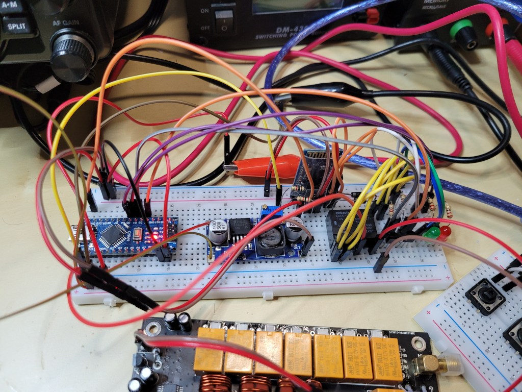
The slave module consists of the following components:
| Arduino NANO | 1pc | The Arduino NANO board |
| HC-05 | 1pc | The HC-05 bluetooth module in the slave mode |
| DC/DC | 1pc | Step-down converter 12V->5V (e.g. with LM2596) |
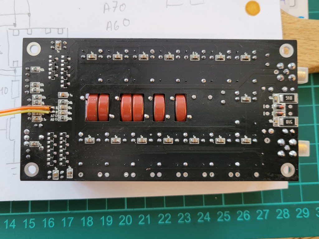
| RELAY | 1pc | G6CK-1114P-US-3DC bistable relay |
| Q1, Q2 | 2pcs | BS170 N-channel MOSFET transistor |
| D1, D2 | 2pcs | 1N4001 diode |
| D3, D4 | 2pcs | LED various colors (can be skipped) |
| R1, R2 | 1pc | resistor 22Ω |
| R3, R4 | 2pcs | resistor 220Ω |
| R5 | 1pc | resistor 1kΩ |
| R6 | 1pc | resistor 2kΩ |
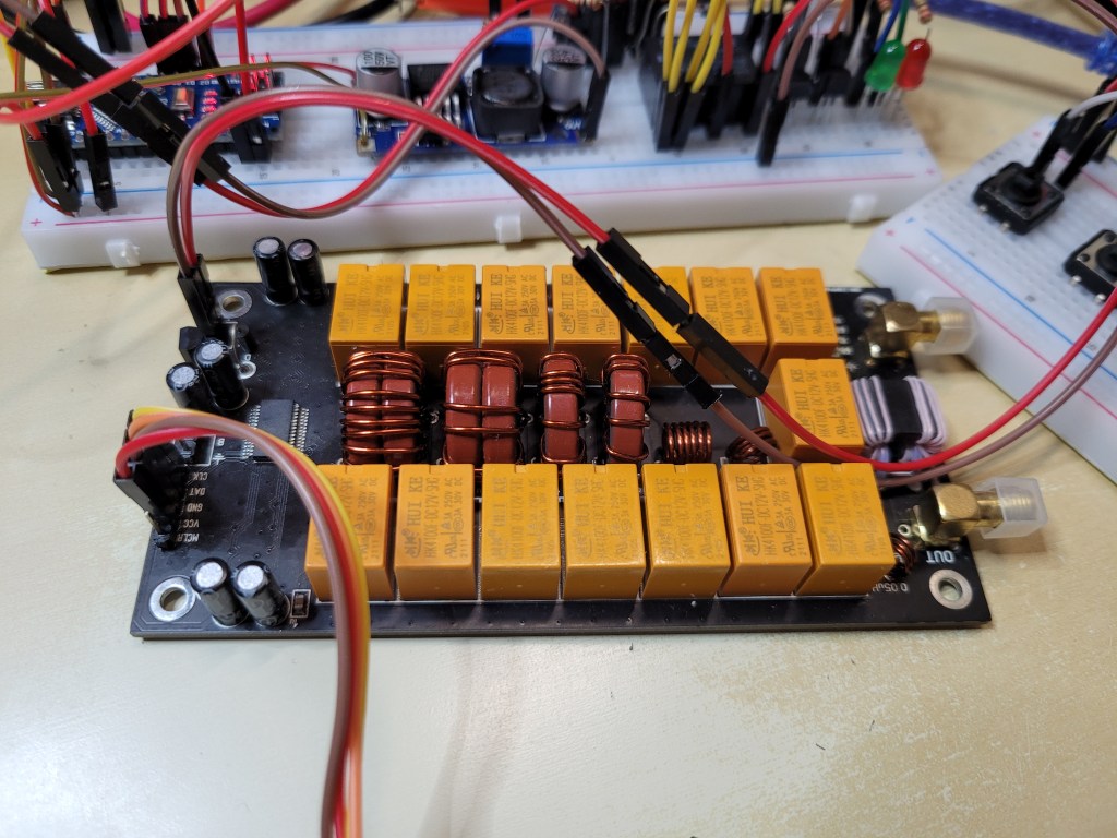
Below is the slave module electric diagram based on Arduino NANO. The bistable relay is used to control the ATU-100 12V power supply. If the POWER button on the master module is pressed the 1st time the tuner is switched ON and the D3 LED is also ON. If the POWER button on the master module is pressed the 2nd time the tuner is switched OFF and the D3 LED is also OFF. The Arduino NANO pins D4, D5 drives the Q1 and Q2 mosfet transistors which are used to drive the SET and RES coils of the bistable relay. The Arduino NANO pins 8-10 drives directly the tuner inputs for the RESET/TUNE, AUTO and BYPASS. If the appropriate button on the master module is pressed the appropriate tuner input is set to 0 because the tuner uses negative logic for the RESET/TUNE, AUTO and BYPASS buttons.
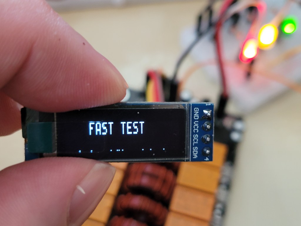
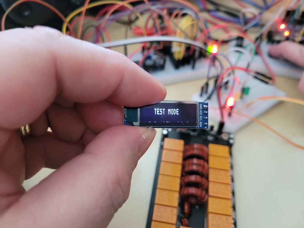
The combinations of the simultaneously pressed the buttons AUTO+BYPASS+POWER and RESET/TUNE+AUTO+BYPASS+POWER is also supported so it is possible to start the tuner in the TEST MODE and the FAST TEST MODE.
The permanently lighting LEDs on the small breadboard (RED, YELLOW, GREEN) are not present in the electric diagram below because those were just used for the better presentation of the tuner negative logic. If the RESET/TUNE or AUTO or BYPASS button or their combination the appropriate LED(s) is(are) switched OFF.
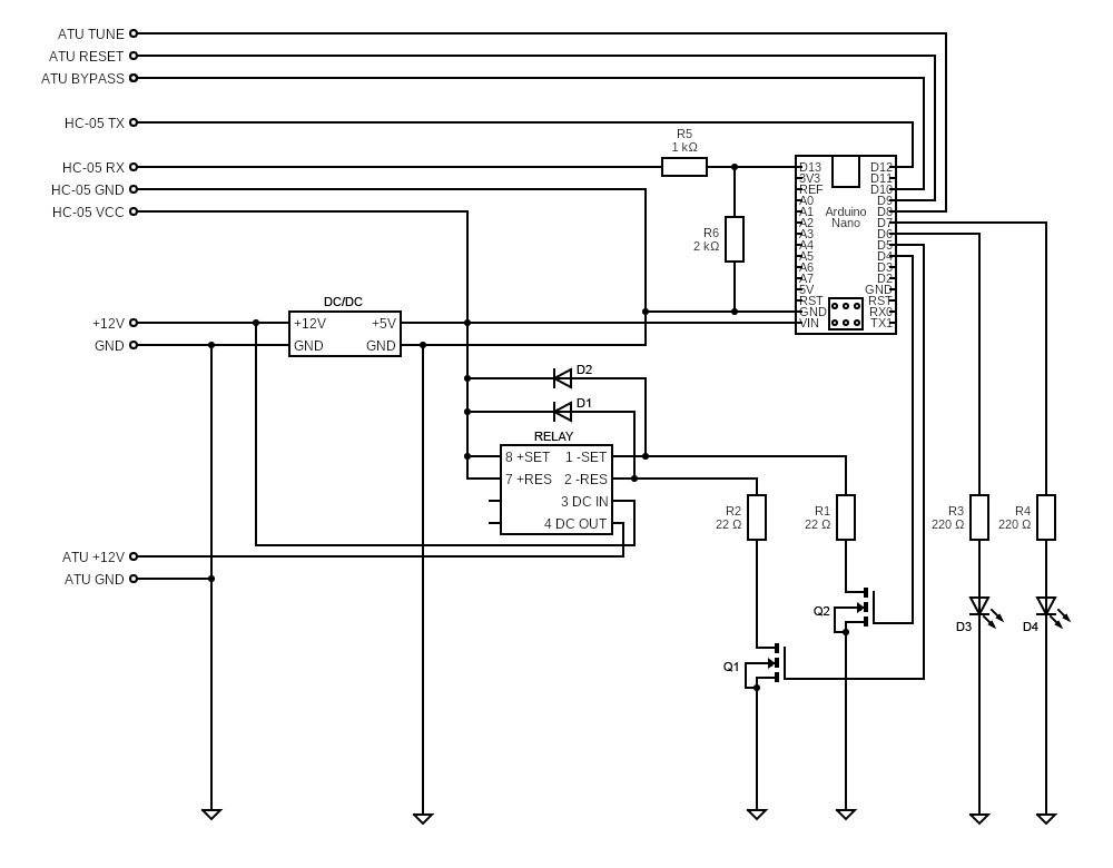
This project is no more developed and is switch to the ESP32 boards therefore I haven’t develop the Arduino sleep mode and wake up via bluetooth. The Arduino pins D2 and D3 can be used for those purposes.
The slave module code for the Arduino IDE:
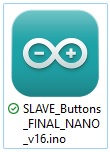 | You can download the SLAVE_Buttons_FINAL_NANO_v16.ino file by clicking on the link on the left or you can copy the code via clipboard from the text filed below. |
/*********************************************************************************************
 * N7DDC ATU-100 All Buttons Bluetooth Remote Control                                        *
 * Final Development testing version v16 (SLAVE), 22.03.2023                                 *
 * SLAVE_Buttons_FINAL_NANO_v16.ino C++ code for the slave module                            *
 *                                                                                           *
 * PWR button fully functional, RESET/TUNE, AUTO, BYPASS buttons fully functional            *
 * (including combinations: AUTO+BYPASS+POWER & RESET/TUNE+AUTO+BYPASS+POWER)                *
 * Power control LED fully functional; RESET/TUNE, AUTO, BYPASS control LED fully functional *
 *********************************************************************************************/

#include <SoftwareSerial.h>                       // Including SoftwareSerial library
//
#define PWR_SET 4                                 // PIN to SET the RELAY coil
#define PWR_RES 5                                 // PIN to RESET the RELAY coil
#define LED_PWR 6                                 // PIN to set the power control LED ON/OFF
#define LED_BUTTONS 7                             // PIN to set the TUNE/RESET, AUTO, BYPASS control LED ON/OFF
#define BTN_TUNE 8                                // PIN to control the TUNE/RESET tuner function
#define BTN_AUTO 9                                // PIN to control the AUTO tuner function
#define BTN_BYPASS 10                             // PIN to control the RESET tuner function

#define	BIT_PWR 8
#define	BIT_TUNE 4
#define BIT_AUTO 2
#define BIT_BYPASS 1

boolean power;

SoftwareSerial btConnection(12, 13);			        // Serial communication RX/TX

void setup()
{
  pinMode(PWR_SET, OUTPUT);
  pinMode(PWR_RES, OUTPUT);
  pinMode(LED_PWR, OUTPUT);
  pinMode(BTN_TUNE, OUTPUT);
  pinMode(BTN_AUTO, OUTPUT);
  pinMode(BTN_BYPASS, OUTPUT);
  pinMode(LED_BUTTONS, OUTPUT);

  digitalWrite(PWR_SET, LOW);                     // Set the relay SET coil to OFF state
  digitalWrite(PWR_RES, LOW);
  digitalWrite(LED_PWR, LOW);
  digitalWrite(LED_BUTTONS, LOW);
  digitalWrite(BTN_TUNE, HIGH);
  digitalWrite(BTN_AUTO, HIGH);
  digitalWrite(BTN_BYPASS, HIGH);

  power = false;

  pinMode(12, INPUT);				                      // Serial communication set the RX pin to INPUT
  pinMode(13, OUTPUT);				                    // Serial communication set the TX pin to OUTPUT
  Serial.begin(9600);                             // Serial communication speed for testing purposes
  btConnection.begin(9600);                       // Bluetooth communication speed; must be equal to the speed set on the both BT modules
}

byte edge = 0;

void loop()
{
  byte btCmd;
  if (btConnection.available())		                // Bluetooth connection availability test
  {
   btCmd = btConnection.read();                   // Decoding received data from the master module
   Serial.println((char)btCmd);
   btCmd -= btCmd > '9' ? 7 : 0;
   if (!edge)
   {
     if (btCmd & BIT_PWR)
      edge = 1;
   }
   if (edge == 1)
   {
     if (!(btCmd & BIT_PWR))
    {
      edge = 0;
      power = !power;
    }
   }
   // The tuner power control (POWER BUTTON); switch the tuner ON/OFF
   Serial.println(edge);                                                // Print value on the serial monitor
   Serial.println(power);                                               // Print value on the serial monitor
   digitalWrite(LED_PWR, power ? HIGH : LOW);                           // Power LED ON/OFF control; if HIGH switch the power LED ON
   digitalWrite(PWR_SET, power ? HIGH : LOW);                           // Relay SET coil control; if HIGH switch the tuner is ON
   digitalWrite(PWR_RES, !power ? HIGH : LOW);                          // Relay RES coil control; if HIGH switch the tuner is OFF


   // The tuner RESET/TUNE, AUTO, BYPASS control
   digitalWrite(LED_BUTTONS, (btCmd & BIT_TUNE) || (btCmd & BIT_AUTO) || (btCmd & BIT_BYPASS) ? HIGH : LOW);  // Turn ON the buttons control LED if RESET/TUNE or AUTO or BYPASS button is pressed
   digitalWrite(BTN_TUNE, btCmd & BIT_TUNE ? LOW : HIGH);                                                     // RESET/TUNE button control; negative logic; if LOW the RESET/TUNE button is pressed
   digitalWrite(BTN_AUTO, btCmd & BIT_AUTO ? LOW : HIGH);                                                     // AUTO button control; negative logic; if LOW the AUTO button is pressed
   digitalWrite(BTN_BYPASS, btCmd & BIT_BYPASS ? LOW : HIGH);                                                 // BYPASS button control; negative logic; if LOW the AUTO button is pressed
  }
}
Gallery: