Due to the highest local QRM especially within evenings I decided to give a try to the DIY KIT of QRM eliminator X-Phase. I bought the kit from RA0SMS. You can find the details here. I also bought a Mini-Whip HF,VLF active RX antenna, 10kHz to 30MHz (with power splitter) which I want to use as the AUX antenna for the QRM eliminator from the same seller.
I split the project to the four separate parts:
- The X-Phase QRM eliminator DIY kit assembling
- The Xiegu CE-19 port replicator modification for use with X-Phase eliminator with the PTT cable connection security circuit
- The PTT cable connection security circuit design and assembling
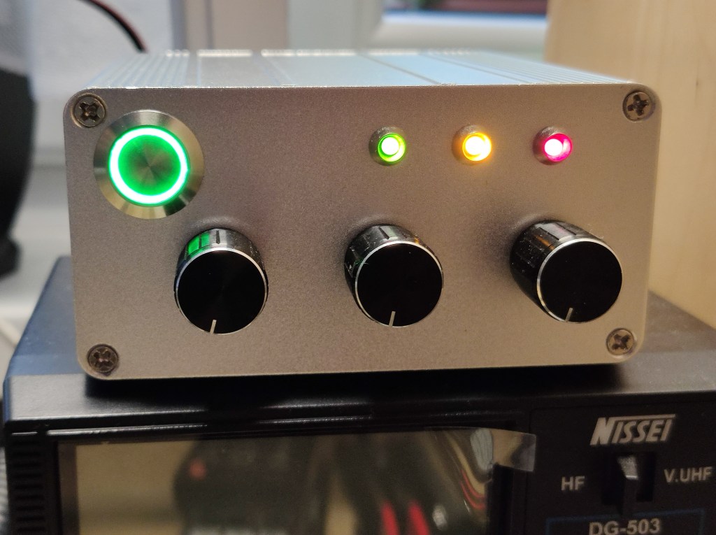
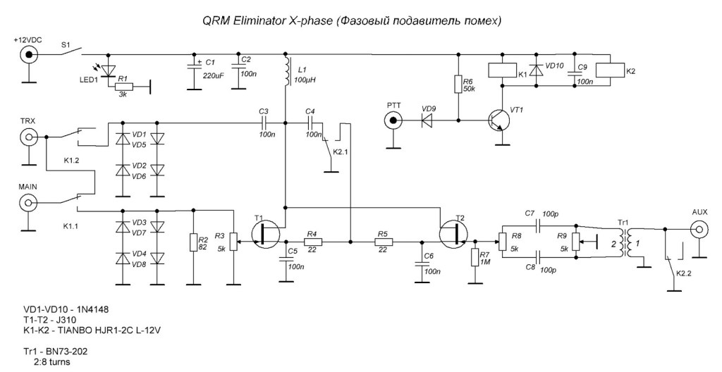
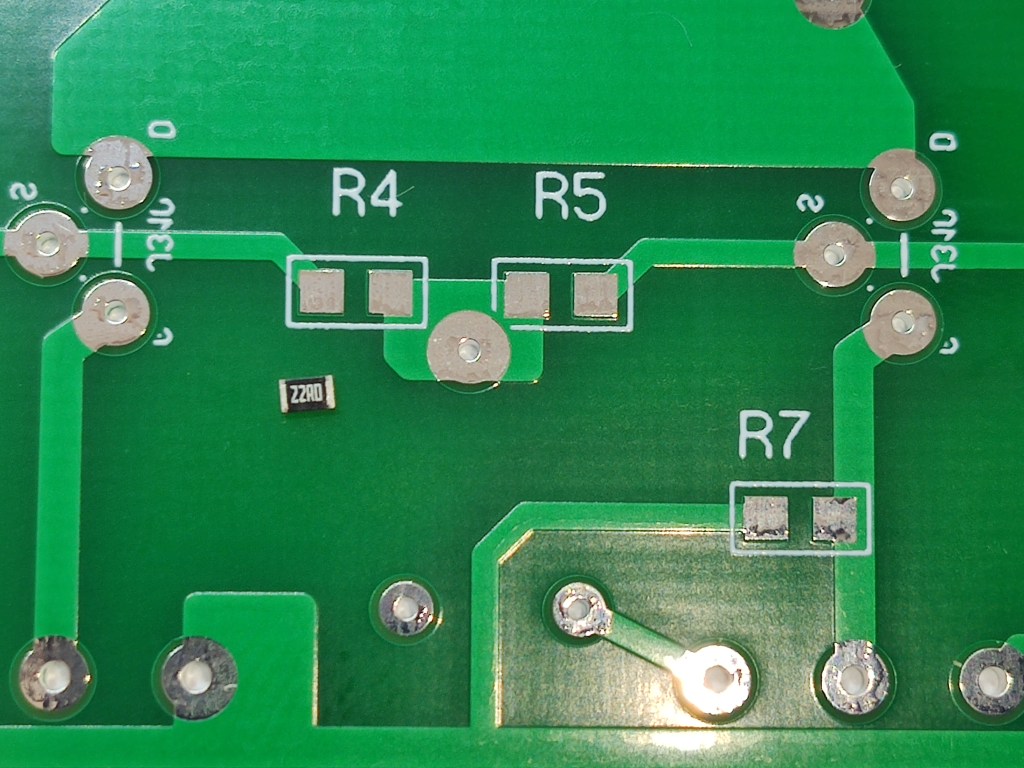
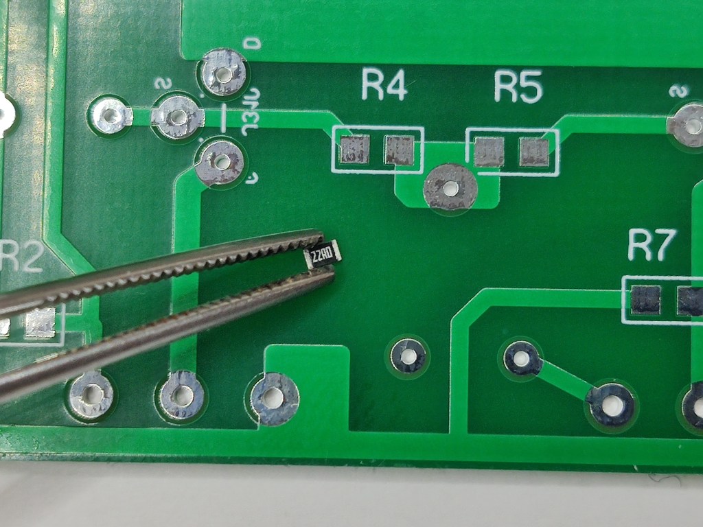
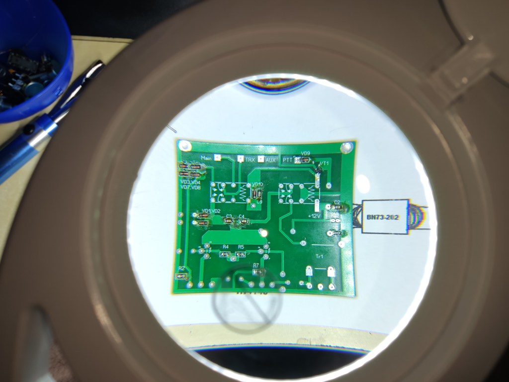
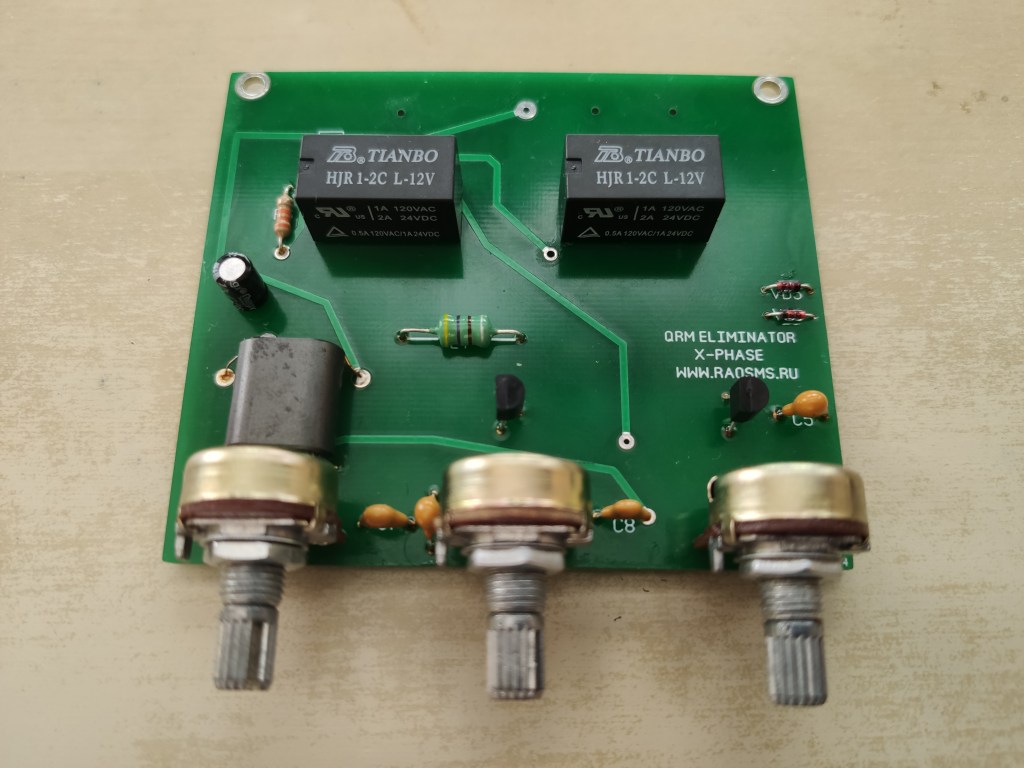
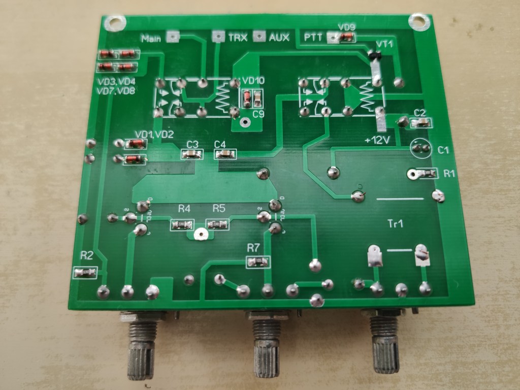
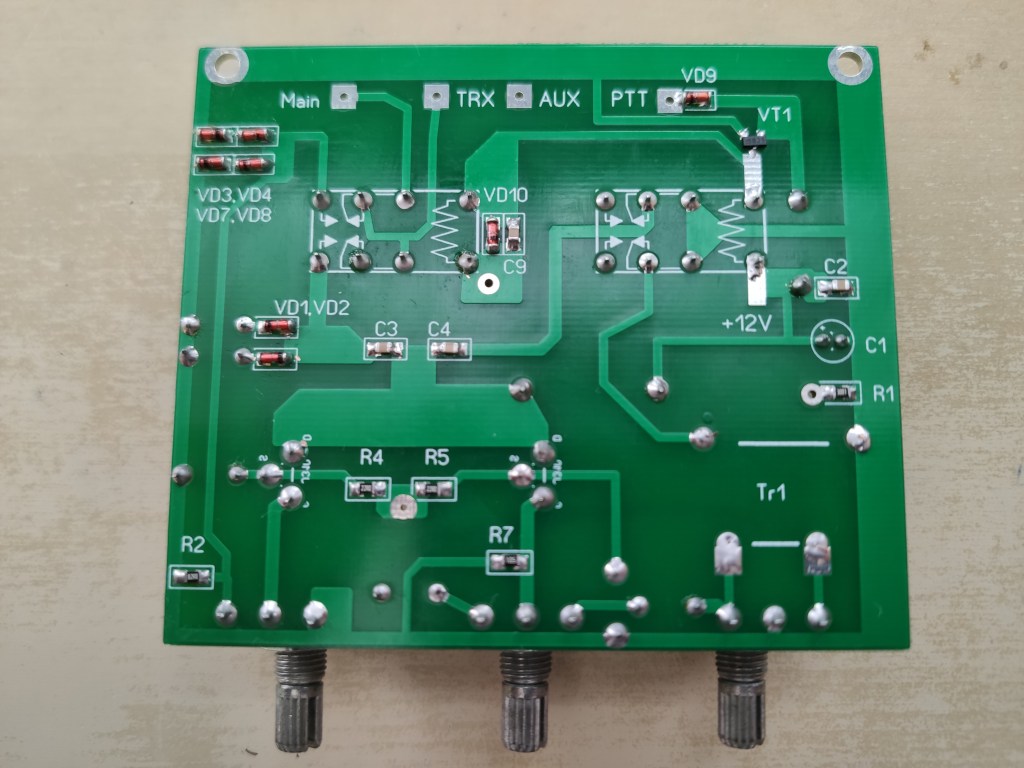
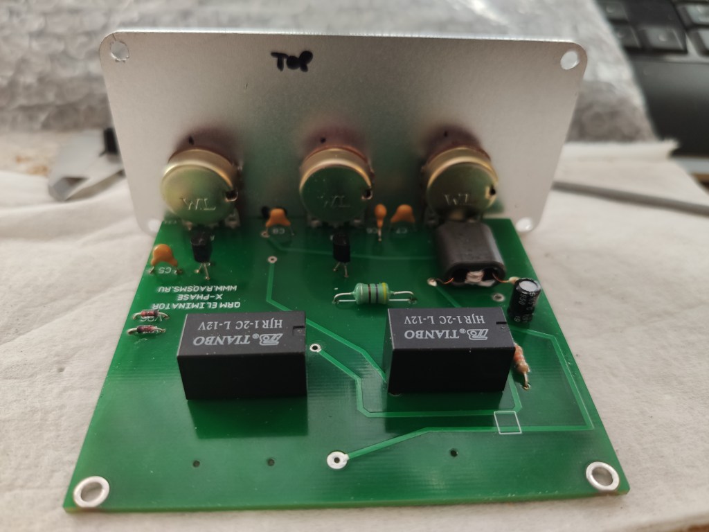
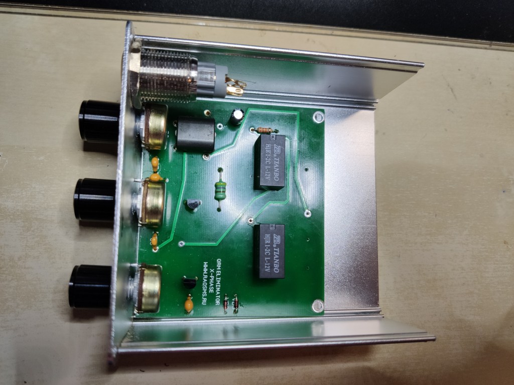
X-Phase QRM eliminator assembling
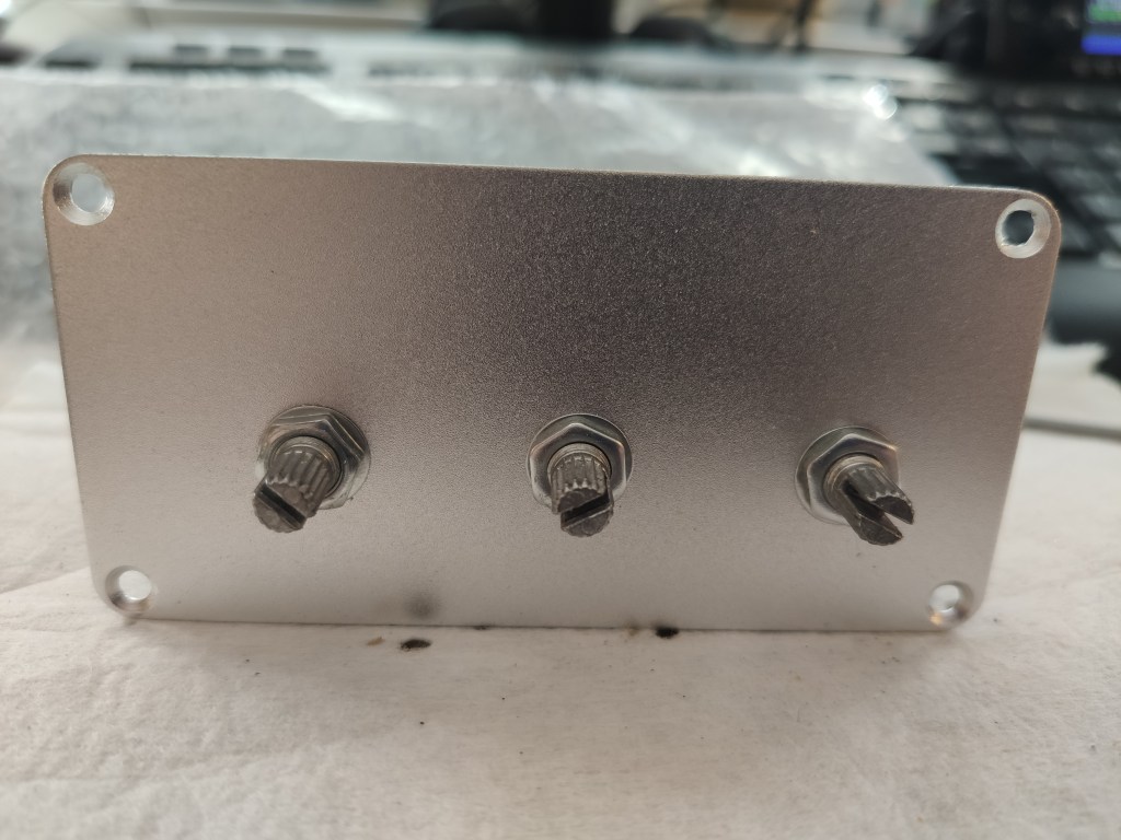
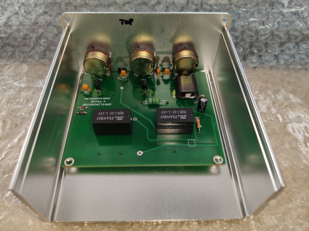
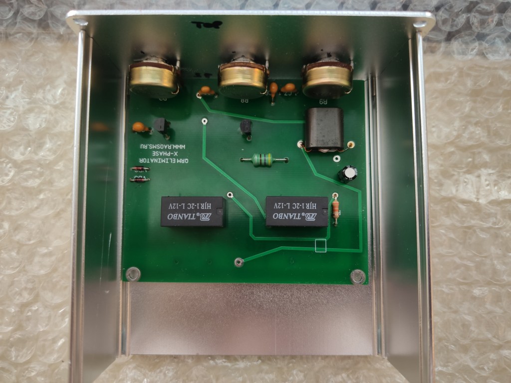
Placing in the box The next part can be helpful for beginners which are starting with their first projects as I am.
I was a bit afraid to start this project because it was first time when I worked with SMD components. At the end it wasn’t so difficult as I expected. The aluminium box was ordered from eBay.


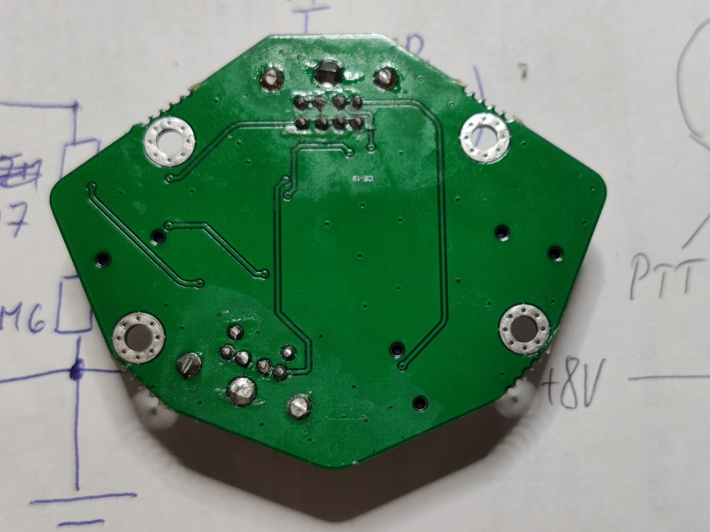
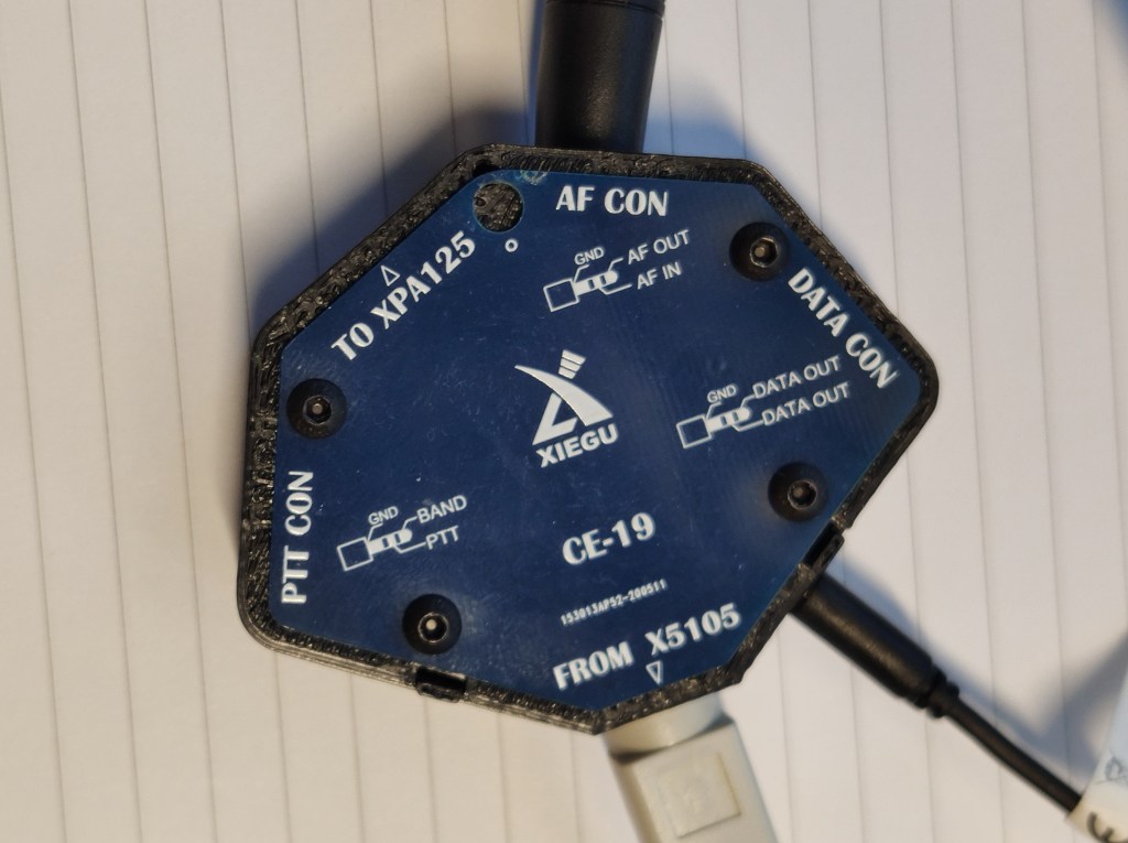
Xiegu CE-19 modification
The QRM eliminator needs a PTT signal from the TRX to bypass the modul when transmitting. Because I wanted to be sure that the PTT cable is always connected to the eliminator / TRX I decided to use a security circuit to avoid its damage.
This circuit is checking if the cable is connected to the TRX and QRM eliminator on both sides. If the the cable is disconnected from TRX and/or from the QRM eliminator the circuit disconnects the QRM eliminator from its power supply and the signal is bypassed directly to the antenna.
The circuit uses the +8V pin to check the connection therefore I needed 2 signals from my G90 (PTT, +8V) and GND.
I also plan to by Xiegu XPA125B and use with my CE-19 module which I also use for the digital modes I decided to modify my CE-19 and add another stereo 3.5mm female connector with PTT, +8V and GND.
The modification was easier because I have my CE-19 placed in an 3D printed box and therefore the adding of 3.5mm female stereo Jack connector was pretty easy.


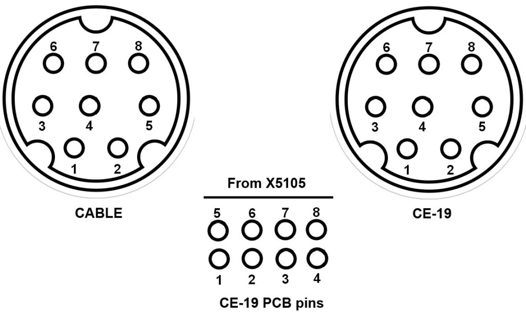

PIN descrtiption
Cable 8 PIN miniDIN
CE-19 PCB PIN
CE+19 8 PIN miniDIN
1- PTT
7- GND
8- +8V
1- +8V
2- GND
7- PTT
2- PTT
6- +8V
7- GND
The PIN layout is described from the front view on the connectors pins. The PCB pins 5-8 are closer to the top of the PCB close to the „From X5015“ connector.
PTT cable connection security circuit

The PTT security circuit was designed by OK1BVK. The circuit controls if the PTT cable (+8V, PTT, GND) is connected to my Xiegu G90 on one side and to the PTT elminiator on the other side. If one or both ends are not connected the circuit cuts off the power supply of the QRM eliminator and the device is bypassed.
